So having got openwrt running on my webcam I now wanted to be able to point the turret and use the various other features of the camera. First of all the DTS (and the one it includes) for the WanView, and indeed most of the RT5350 devices in openwrt, doesn’t give access to some of the GPIOs. So after creating a custom board and generally tidying things up, the reverse engineering could begin:
GPIO 0, active low, reset button
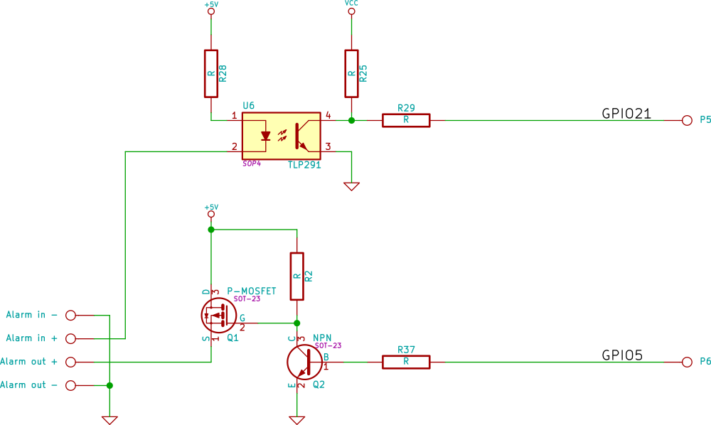
GPIO 5, active high, alarm out (see schematic)
GPIO 12, active high, green led on camera
GPIO 13, active low, orange led on ethernet connector
GPIO 21, active low, alarm in (see schematic)
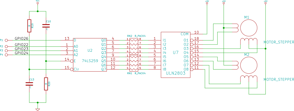
GPIO 22, motors A0 (see schematic)
GPIO 23, motors A1 (see schematic)
GPIO 24, motors A2 (see schematic)
GPIO 26, motors D (see schematic)
The motor driver is particularly special. The motors are typical 5-wire unipolar stepper motors. I’d normally expect these to be driven with the canonical full step waveform, but the interface circuit makes that impossible. The 4 GPIOs from the cpu pass to a 74HC259 8 bit transparent addressable latch, which has its enable input strapped true. This design means the only thing the CPU can do is set all the bits in the latch to the same value by cycling through all the values of A0,1 and 2, and then change one other bit by setting A0, 1 and 2 and finally inverting D. That means we can only power one coil at once and so the stepper motors have to be wave driven.
TP-C516 motor driver schematic
But for real brokeness the alarm output is the clear winner:
TP-C516 Alarm circuitry
Yes the mosfet’s drain and source are swapped and current always flows through the body diode, so if you put an LED on the alarm output, toggling GPIO5 gets you a dim or a bright light.
Putting that knowledge together gives one a perfectly respectable patch for openwrt to support this device. I also added support for 16M ROMs as this device has a sufficiently capable processor, that one might well want to run it as an access point or connect it into a VPN. [I was initially very confused by pinctl/pinmux driver in openwrt. Looking at the code an the output you might think that it can dynamically allocate pin functions. It can but not always, and especially not if overridden by instructions in the DTS]
I wrote a budget character device driver for the motors it creates /dev/motors and if you write U D L and R characters to it it moves the motors one step at a time. I also patched mjpg-streamer so it had on-screen controls. For timing I give the latch 100ns to settle (that’s a good margin for a part running at 3.3V), and step the stepper motor at 50Hz as that seems to be what the original firmware did. One note of caution: it would seem that the motors are not rated for continuous activation of the coils and get exceedingly hot if you try. My driver shuts off the current after 20ms.
Looking at the board:
There’s not much hardware left to reverse engineer, just the audio system which is a job for part 3.
Our office has a number of these Polycom SoundStation 2W devices, and until last month they all worked pretty well. They’re basically a DECT version of the venerable SoundStation 2. (You can in fact throw away the Polycom base-station and replace it with a SIP enabled one and get an excellent cordless SIP conference phone). In the version of the firmware ours had you could even use two of them at once with the same base station at the same time to get better coverage for a large room.
If you know much about DECT that last statement should have you worried: how do two devices manage to get the same randomly generated private key? That question has one obvious answer.
There’s not much hardware available for playing with DECT. You could use an SDR and I’ve a goodly number of them, but I’m not aware of there being a particularly good stack. The answer is a bizarre evolutionary dead-end of wireless technology: the idea was that you got a special DECT base station, hooked it up to BRI ISDN port, put one of these or one of these
A type III (yes really) DECT PC card.
in one’s PC, and then, one could surf the internet at a blazing 128 kilo-bits a second (or your could share and two could get 64 k) – all without wires. [These things come up on eBay every now and then if your’re curious, I paid €47 for one and a PCI to PCMCIA bridge to put it in]. Once you have one of these and have coaxed the Linux driver into working there’s a goodly selection of software to play with. I used dedected.
There are a few alarming things you’ll discover when you start poking the various bits of DECT hardware you own. The ones that got me were that key presses on the handset are sent en-claire even if the audio is encrypted, and if you have a plurality of manufacturer’s handsets connected to a base station it’s quite likely that your audio isn’t encrypted either.
From the research i did the Polycoms did appear to have a fixed key, but it’s rather hard to generate a known plain-text using a microphone. Fortunately they do have a mini USB port, and I was led to believe that if I upgraded I’d get encryption. Polycom provide, once one’s fought their CMS and agreed to export restrictions, the latest firmware upgrade, so this should be a simple upgrade. However this is Polycom and some caution is required.
To this end I purchased another console (the bit that looks like a Frisbee) from eBay and applied the firmware update to it. It took a few goes, as there’s a goodly number of race conditions between windows installing drivers and upgrade waiting for a response from them but the experience was mostly painless. I then connected it to one of our base stations and it worked, but then the misery started: one by one the other consoles in the office lost contact with their base stations and refused to talk to them or register any more. Worse the option to pair with a DECT/GAP base station had disappeared from their menus. Woe. Caution had failed me. I tried giving the same new firmware update to the sick Polycoms, but without success.
The insides of the SoundStation 2W
Internally the 2W has a Xilinx CPLD, a TMS320 which is the main CPU and a DECT “Cordless Voice Module” SC14CVM. The TMS320, its RAM, ROM and JTAG connector are all hidden under a particularly-well-soldered-on screening can. What you can easily get at, is a small I2C EEPROM, an at24c32, that sits on the CVM. Swapping the contents of this ROM between the working and not-working consoles didn’t, however, bring any joy.
The next step was to tear apart the firmware: fortunately the firmware updater leaves this lying around in conventional formats. strings(1) on the TMS320 firmware isn’t initially rewarding until you remember that the TMS320 has 16 bit words and so you need to use the “-e l” option to strings. Looking at the output of strings there are two hidden menus in the firmware: one looks to be for test, and the other for diagnostics. It took a few minutes of finger pressing to find out how to get into them: Holding the up-arrow and star gets you into the tests menu, and holding the down-arrow and mute gets you into the diagnostics menu.
The hidden diagnostics menu
From here you have a few options: one allows to read and write values on the CVM EEPROM either in the console or the base (That explained how our rogue console managed to kick everyone else off.), another sets a country code.
The country code menu.
The working Polycom had a country code of 22000205, all the others had one of 0. It appears that 0 is the default. The consoles appear to set the country code of any base stations they find to their own, and will only pair with base stations that match their country code or have country code 0. Programming our remaining consoles with 22000205 brought them all back on line. All but one of them then took the new firmware update, and their missing options all came back.
The one that didn’t was on such an old version of the firmware that the updater wouldn’t update it. Much Googling revealed that we needed an intermediate firmware version from Polycom. Polycom only deal with resellers so that wasn’t a solution. So off came the screening cans:
Component side.Solder side.
My first plan was to clamp a high-ish address line of the ROM during the two seconds at boot when the bootloader CRCs the firmware image in the hope that, after noticing the image was corrupt, it would then go into a recovery mode and the update software would take it from there. When I tried, the bootloader duly noticed and did go into a please-upload-new-firmware loop. Unfortunately the firmware updater still didn’t want to play. No dice.
My second plan was to solder a header onto what looked like a standard TMS320 jtag port and see if I could make any sense of the ROM contents. Despite my best efforts nothing could get what should have been the TDO pin to budge, again, no dice.
Where the JTAG wasn’t
So that just left the third option, take the TMS320’s ROM off. (It’s an Am29LV400BB. Which tells us that the bootloader is at the beginning of the ROM.) So I did that, connected it to my TL866 programmer and read out the contents. I looked at the layout of the data. It matched what I was expecting. So I created a new ROM, by taking the bootloader from the update software and combining that with the application that I had just read from the ROM, but with one English word in the application changed, so the CRC would fail.
I tried programming the flash, but my TL866 said “No”, and that made me sad. I tried flashing the original contents of the ROM, and the TL866 said “No” again: more sadness. After poking at the rom with a scope it appears that the TL866 doesn’t cope well with ROMs that have a BYTE# pin and thus can change between 8 and 16 bit widths. Disconnecting that line from the programmer and shorting it to VCC made the programmer happy.
The modified TL866 adapter.
However, now I realized that every other byte in the copy of the firmware I had taken was corrupt. In desperation I tried flashing the complete firmware file onto the ROM, and soldering the ROM back into the Polycom. Nothing. Not even an LED. Still no dice.
Finally, not relishing the prospect of getting another screening can off to get a good copy of the ROM from one of the other Polycoms, I realized that the firmware files had a 4 byte header giving the length of the file. Stripping that off, de-soldering the ROM, re-flashing, and re-soldering got me a Polycom that booted, but wasn’t so happy. I then re-flashed it to program in the new CVM firmware, and it worked like a charm.
So I find myself needing some more el-cheapo pan-and-tilt webcams. The last time I did this, I bought the cheapest thing I could from eBay and was pleasantly surprised to find that pretty much all the devices ran a small embedded linux, had a perfectly usable web interface and had a connector on the rear that could be used to trigger the sending of a email with captured pictures. Buoyed by past experience I ordered some more: in this case the cheapest on ebay which had the connector on the rear: the KK Moon Model 801 TP-C516.
KKMoon TP-C516
They duly arrived and I connected one to a test network. It dhcp’d an address, and began trying to talk to a server in LA. There was no web interface, and the only interesting thing nmap(1) could find was telnet. After some fettling I managed to log in with the username and password of root and anni2013. A quick look around confirmed it was running Linux. I spent an hour or so trying to find more conventional firmware without success, so I then had a look at the CPU. The camera is built around a Ralink RT5350 wifi SoC. I’ve previously ported gcc and openwrt to a similar ralink CPU, and it was a Sunday morning so I thought I might have a shot.
The camera has 32M of SDRAM and 8Mb of SPI flash in an mx25l6406e (or rather a clone). So I took the chip off and read it. The bootloader was, predictably at the beginning of the rom, and appeared to have a serial output, so the next step was to find where that came out on the hardware. A little bit of judicious hunting found two test-points next to the SPI rom.
Connecting those up and knowing from the dump of the rom that it was expecting 57600 baud gave the following:
U-Boot 1.1.3 (Oct 31 2012 - 23:46:19)

Board: Ralink APSoC DRAM: 32 MB
relocate_code Pointer at: 81fb4000
sysctl:40200300
spi_wait_nsec: 42
spi device id: c2 20 17 c2 20 (2017c220)
find flash: MX25L6405D
raspi_read: from:30000 len:1000
.raspi_read: from:30000 len:1000
.============================================
Ralink UBoot Version: 3.5.3.0
--------------------------------------------
ASIC 5350_MP (Port5<->None)
DRAM_CONF_FROM: Boot-Strapping
DRAM_TYPE: SDRAM
DRAM_SIZE: 256 Mbits
DRAM_WIDTH: 16 bits
DRAM_TOTAL_WIDTH: 16 bits
TOTAL_MEMORY_SIZE: 32 MBytes
Flash component: SPI Flash
Date:Oct 31 2012 Time:23:46:19
============================================
icache: sets:256, ways:4, linesz:32 ,total:32768
dcache: sets:128, ways:4, linesz:32 ,total:16384

 ##### The CPU freq = 360 MHZ ####
 estimate memory size =32 Mbytes

Please choose the operation:
 1: Load system code to SDRAM via TFTP.
 2: Load system code then write to Flash via TFTP.
 3: Boot system code via Flash (default).
 4: Entr boot command line interface.
 7: Load Boot Loader code then write to Flash via Serial.
 9: Load Boot Loader code then write to Flash via TFTP.
 0

3: System Boot system code via Flash.
## Booting image at bc050000 ...
raspi_read: from:50000 len:40
. Image Name: Linux Kernel Image
 Created: 2014-10-30 1:46:36 UTC
 Image Type: MIPS Linux Kernel Image (lzma compressed)
 Data Size: 3044465 Bytes = 2.9 MB
 Load Address: 80000000
 Entry Point: 8041b000
raspi_read: from:50040 len:2e7471
............................................... Verifying Checksum ... OK
 Uncompressing Kernel Image ... OK
No initrd
## Transferring control to Linux (at address 8041b000) ...
## Giving linux memsize in MB, 32

Starting kernel ...


LINUX started...

 THIS IS ASIC
Linux version 2.6.21 (root@sky) (gcc version 3.4.2) #1071 Thu Oct 30 09:46:24 CST 2014
Initrd not found or empty - disabling initrd
Kernel command line: console=ttyS1,57600n8 root=/dev/ram0
So I next had a look at the openwrt side. Pleasantly openwrt trunk already had support for a non-PTZ camera based on the RT5350 (The WansView NCS601W).
Building that and feeding it to the bootloader’s option 2 via TFTP got me up and running almost immediately. Building mjpg-streamer (after fixing a bug which caused gcc’s stack canary to trip) gave me an, albeit upside-down, streamed image. Success, and all before breakfast! The next task was figuring out how to move the turret.