
So having got openwrt running on my webcam I now wanted to be able to point the turret and use the various other features of the camera. First of all the DTS (and the one it includes) for the WanView, and indeed most of the RT5350 devices in openwrt, doesn’t give access to some of the GPIOs. So after creating a custom board and generally tidying things up, the reverse engineering could begin:
- GPIO 0, active low, reset button
- GPIO 5, active high, alarm out (see schematic)
- GPIO 12, active high, green led on camera
- GPIO 13, active low, orange led on ethernet connector
- GPIO 21, active low, alarm in (see schematic)
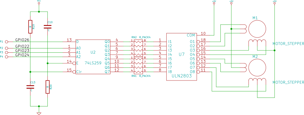
- GPIO 22, motors A0 (see schematic)
- GPIO 23, motors A1 (see schematic)
- GPIO 24, motors A2 (see schematic)
- GPIO 26, motors D (see schematic)
The motor driver is particularly special. The motors are typical 5-wire unipolar stepper motors. I’d normally expect these to be driven with the canonical full step waveform, but the interface circuit makes that impossible. The 4 GPIOs from the cpu pass to a 74HC259 8 bit transparent addressable latch, which has its enable input strapped true. This design means the only thing the CPU can do is set all the bits in the latch to the same value by cycling through all the values of A0,1 and 2, and then change one other bit by setting A0, 1 and 2 and finally inverting D. That means we can only power one coil at once and so the stepper motors have to be wave driven.
But for real brokeness the alarm output is the clear winner:
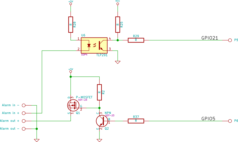
Yes the mosfet’s drain and source are swapped and current always flows through the body diode, so if you put an LED on the alarm output, toggling GPIO5 gets you a dim or a bright light.
Putting that knowledge together gives one a perfectly respectable patch for openwrt to support this device. I also added support for 16M ROMs as this device has a sufficiently capable processor, that one might well want to run it as an access point or connect it into a VPN. [I was initially very confused by pinctl/pinmux driver in openwrt. Looking at the code an the output you might think that it can dynamically allocate pin functions. It can but not always, and especially not if overridden by instructions in the DTS]
I wrote a budget character device driver for the motors it creates /dev/motors and if you write U D L and R characters to it it moves the motors one step at a time. I also patched mjpg-streamer so it had on-screen controls. For timing I give the latch 100ns to settle (that’s a good margin for a part running at 3.3V), and step the stepper motor at 50Hz as that seems to be what the original firmware did. One note of caution: it would seem that the motors are not rated for continuous activation of the coils and get exceedingly hot if you try. My driver shuts off the current after 20ms.
Looking at the board:


There’s not much hardware left to reverse engineer, just the audio system which is a job for part 3.
Hi James,
do you have a compiled image, that you can send me?
Did you work on part3, the audio functions?
Hi!
I came here looking for a way to install Debian on my Kobo Glo HD. Great blog!
I just read your two posts about the Debian installation (https://wordpress.panaceas.org/wp/index.php/2017/01/17/kobo-glo-sic-hd-hacking-part-2/), but I think I don’t have the technical knowledge that is necessary to do these kinds of things.
I was wondering if it would be possible to get a copy of your SD card with the Debian installation? That way I could download your image, write it to one of my SD cards and I would have a working installation of Debian.
Thank you very much for your work.
Nicolás
Hey Misery, I have this piece of crap webcam and the website for it is scc21.net
Thing is I would like to use it with ispy but I can’t find any way of connecting with the stream from this 801. Nothing is working for me only its own crappy software which tilts and pans and that’s all.
Is there a way I could flash it or something to get it to output a stream ispy would recognise?
Cheers
Hi James. Hoping you can help. I have a Tenvis JPT3815w ip camera. The turret hardware control is basically the same as the TP-C516 motor driver schematic. Trying to interface to an Arduino, so I can use a camera program through the camera to remote control other things. I know in software you send either a positive or negative number of steps to control the direction of the stepping motors. But I cannot find a signal on the 74HC259 that changes the directions (CW/CCW). I find a signal the controls the up/down vs the left/right motors. The D signal providing the steps. But I have not been able to determine how the fields are reversed. The mode pins appear to stay the same. I don’t seem to capture a phase change if the D signal to anything else. How specifically is the software telling the hardware to reverse the stepping motors directions? Thanks.
I’ve come across many helpful things on the web site about personal computers. Even so, I have got your thoughts and opinions in which notebook computers continue to be less than powerful enough becoming a sensible choice in the event you usually do jobs that require plenty of strength, such as movie enhancing. Nevertheless for world-wide-web browsing on, word running, and many some other popular computer work these are perfectly, supplied you may not mind the tiny screen size. Many thanks discussing your thinking.