Low-level debugging on modern laptops

If your day job involves writing code that runs inside or underneath operating system kernels, you often find yourself wishing for a simple way of getting debug prints out. Years ago this was simple, about 12 lines of code would set up a serial port and and then mov dx,3f8H; out dx,al would make a character magically appear on the terminal.

Serial ports have long since gone the way of the stone axe, and their replacements aren’t really any good: AMT’s SOL is a pain to use, USB 2 and 3 debugging is miserable to set up, works about one in 20 times you want to use it and needs to be connected at boot, firewire’s disappeared as have all expresscard slots.

The JNT-PAD, England’s finest terminal concentrator.

Serial ports were good because you could usually persuade the rest of the OS stack to leave them alone, and they needed minimal configuration (they don’t even require functioning RAM) to work.

Frustrated by this, I came up with two new solutions to this problem, one which requires about $10 of hardware and is useful in the lab, and one the requires no hardware and is useful in the field, neither require anything other than IO port access and the CPU’s TSC to function (no DMA, no memory buffers &c.)

1) PSK using the PIT and the speaker:

You can get usable (1000 baud) simplex debug data using just the PC speaker. This is good as it doesn’t require any extra hardware except another PC or smart-phone to decode the squeaks.

The PC AT contained an intel 8254 programmable interval timer (PIT), it was used to generate a periodic ticker interrupt, refresh the DRAM, and generate the signal for the PC speaker. The (edited) schematic looked like this:

Today this is typically all integrated somewhere inside the south-bridge, but the logic is the same. With this arrangement the CPU can directly bit-bang the speaker using bit 1 of port B, or the 8254 can generate square waves.

There’s a long and proud history of transferring serial data over audio, from the old radioteletype systems of the 1930s, through the modems of the dial-up era to horrors like Silverpush’s Unique Audio Beacons. The two most commonly used modulation schemes are Frequency Shift Keying (FSK) and Phase Shift Keying (PSK). FSK is much simpler and lends itself to being generated by the 8254, but PSK is easier to decode in the presence of noise, and tends to work better over the sort of channels formed by laptop speakers and smart-phone microphones. (I got 100 baud with FSK in ideal conditions, vs. 1000 baud with PSK)

A 300 baud FSK modem with rubber cups to hold a telephone handset.

It turns out there’s a standard (ITU 60H0J2B) for simple binary PSK communication over audio channels and it’s still in use by radio amateurs today. A zero is encoded by reversing the phase, and a one is encoded by leaving the phase as it is. The transmission starts with a  string of zeros, and ends with a string of ones, and there’s a fairly arbitrary mapping of characters to strings of ones and zeros.

I had a quick look to see if I could use the 8254 to do PSK. In theory it’s possible to reset the counter halfway through a cycle or to switch between the carrier frequency and double the carrier frequency, but neither of these two approaches seemed particularly reliable or portable, because, I think, a goodly number of the 8254 implementations don’t support the more outré modes.

By far the simplest thing to do is to use the 8254 to calibrate the CPU’s TSC and generate the carrier when the system is idle (keeping the squelch on the receiver happy). Then when the system wants to send data, the CPU can bit-bang the waveform through bit 1 of port B directly in a tight loop timed by the now calibrated TSC. One of the nice, but crazy, things about Linux is that a user-land processes can have have direct control of the interrupt flag and the ability to write to IO ports. So using that capability, here’s a quick demonstration of the system as a small Linux program, you’ll need to run it as root, and, obviously, since it steals a CPU from the system for the duration, you probably shouldn’t run it on something you care too much about. (If your OS has loaded a sound driver it’s possible that the 8254 output is muted in the mixer, Linux usually calls this channel something like Beep.)

Simple mixer control 'Beep',0
Capabilities: pvolume pvolume-joined pswitch pswitch-joined penum
Playback channels: Mono
Limits: Playback 0 - 15
Mono: Playback 13 [87%] [-6.00dB] [on]

To receive the data you’re spoilt for choice, the applications I found most useful were fldigi on the desktop and, on android, tivar. Here’s a screenshot of tivar running:

You’ll need to set the mode to match the modulation and baud rate (here BPSK and 125) and set the carrier frequency (Menu → Preferences → MODEM → Audio Frequency) to match F in the source (here 2200 Hz). Experimentally 1k baud works fine for a well-placed, good-quality microphone in a quiet room.

One of the interesting things about this approach is that you get to hear when SMM steals CPU cycles.

2) Full duplex serial over DisplayPort:

The vast majority of DisplayPort outputs are actually dual-mode (or DisplayPort++). With the appropriate magic they will generate DVI compatible signals, albeit at the wrong voltage levels. The DVI interface includes the I²C DDC bus, and it’s possible to attach an I²C UART like the SC16IS750 and, GPU permitting, then bit bang it from the CPU. Intel GPUs give you direct access to the DDC lines via some GPIO registers.

If you try this you’ll discover several problems: first it’s not obvious how you tell a DisplayPort++ port that you want it to be a DVI/HDMI port, second the firmware of modern GPUs (and indeed windows) will power down the port at almost every opportunity and third you’ll still need some way of getting the TTL data out of your UART at the end since not even desktops tend to have serial ports any longer.

The only reference I can find for switching dual-mode DisplayPort sources is the VESA DisplayPort Interoperability Guideline v1.1. It suggests  that a source will detect an HDMI/DVI adapter by either testing if CONFIG1 is high, or by trying both DisplayPort aux transactions and I²C transactions and seeing which works. Empirically on the Intel chipsets I tried, I needed to pull CONFIG1 high.

Power saving, however, proved more complicated. After a bit of digging it turns out that the output power management and hotplug detection on recent Intel GPUs is done in the GPU’s firmware. I didn’t find any simple way to override it, so I did the next best thing and tricked it: adding a 24c02 to the bus, programmed with valid DDC data, and pulling the hot plug detect line high caused the GPU firmware, and both the EFI and the OS video drivers to keep the port powered.

Finally that leaves the third problem getting the data out  (my desktop also no longer has a serial port). Rather than use a real 24C02 and SC16IS750, I decided to use a small STM32F103RBT6 board I had lying around to emulate them, it, in turn, presents a CDC-ACM USB serial port to the host that’s plugged into it.

The STM32F1 turns out to be an excellent choice: there’s hardware support for both USB and implementing exactly two I²C slaves. Programming the I²C hardware on the STM32F1 is always a bit exciting as the state machine can get stuck easily but the slave support seems much more robust. The only disappointment is that enabling the I²C hardware forces you to disable the pull-ups on the pins, necessitating a small board with external pull ups.

The wiring looks like this:

Pin numbers on the left are for DisplayPort and mini DisplayPort connectors

The code to drive this stack is somewhat simpler than the BPSK modem above, as both the SC16IS750, and my STM32F1 emulation of it present the traditional NatSemi 16550 register set. To improve performance I added a new register to the STM32F1 emulation of the SC16IS750, which allows you to send an arbitrary number of bytes in one I²C transaction (the SC16IS750 increments the register address after every byte). The STM32F1 code is here (I added a small boot-loader that allows the firmware to be updated with dfu-util). I’ve added the pre-compiled hex files to the repository as I know that building the code on Debian is somewhat involved.

Demonstrating this from Linux user-land is challenging. Somewhere between 3.11 and 3.19, Linux made it impossible to map the Intel GPU MMIO bar in user-land. Fortunately Intel has a mechanism to allow their 16 bit video BIOS to access the MMIO bar using only IO port accesses. The code uses that mechanism. It should work on pretty much any recent-ish Intel GPU.  One of the nice things about this approach is that if you know the bus number in advance, you can connect the adapter after the system has booted.

root@yoga3:~/sd# ./serial_over_dp
Found active IGFX I2C bus 3
Found active IGFX I2C bus 4
Serial port found on IGFX I2C bus 4
root@yoga3:~/sd#


Resources:

STM32F1 code: git://git.panaceas.org/stm32/serial_over_dp (note you’ll need to pull the submodule and compile it)

Linux user-land example code: git://git.panaceas.org/tools/serial_debugging (includes hex files of the STM32F1 code)

If making DisplayPort cables seems like no fun, you can get the I²C out with a series of adapters – there are plenty of people on Amazon and eBay selling HDMI screw terminal adapters like this one:

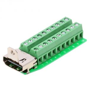
and then you can connect this to a “passive” (read cheap) DisplayPort to HDMI adapter cable. To finish you just have to make a few connexions at the screw terminals:

  • A link from Pin 18 (DP_PWR) to Pin 19 (HPD) to indicate there’s a monitor
  • A 10KΩ resistor form Pin 18 (DP_PWR) to Pin 15 (DDC CLK/SCL)
  • A 10KΩ resistor from Pin 18 (DP_PWR) to Pin 16 (DDC DAT/SDA)

Then connect Pins 15 (SCL), 16 (SDA)  and 17 (Ground) to PB6, PB7 and Ground on the STM32F1 board.

Xerox ColorQube 8570DN Printers

It has finally become impossible to find replacement toner for my trusty Kyocera FS-C5016-DN printer, and even if I could, the developers are running out of iron filings and cost more than the printer to replace, so I started casting around for a good replacement. Colour printers fall basically into two camps: ones which have some ability to control the amount of pigment placed per pixel, and those where it’s all or nothing. For laser printers almost all the manufacturers have given up on continuous tone except Panasonic, but they’ve pretty much given up on the European market. Most of the colour laser printers I looked at where ghastly, and the toner cost more than the printer. Inkjets weren’t an option since as my trusty 20kg Laserjet 4 plus with duplexer costs almost nothing to use, I don’t print colour often enough to prevent the nozzles clogging.

In desperation I looked at the Xerox wax printers. If you’re not familiar with the technology, they work by melting blocks of wax and then squirting the molten wax onto the paper using a piezoelectric head (rather than boiling the ink’s solvent as most inkjets do). This has the advantage, as the ink is already a liquid and doesn’t need a solvent, that the nozzles won’t clog as the solvent evaporates. You can pick up a used ColorQube (presumably misspelled for legal reasons) 8570 fairly cheaply, and they weigh in at a reassuring 27.4kg. Better still a service and maintenance manual is available.

Inside the printer is beautifully made, with endless drive-chains, gears, clutches and heaters, but the ink is eye-wateringly expensive. Worse, Xerox assign the printer a region and it will only accept ink manufactured for that region. It’s the whole misery of DVD region coding over again.  However it’s not as bad as it first looks: the ink’s region is set, not by some chip in a plastic ink carrier (Xerox make a big thing about how the printer is eco-friendly because the ink doesn’t come encrusted in DRM encumbered plastic), but by the physical shape of the ink block. Here’s a European coded black ink block:

There’s a sensor in the printer that determines if there is or is not a notch at the locations “B”, “C” and “D”. The chap at PyroBrit spent some time working out what the various combinations mean:

A D Starter Pack
A C North America
A C D
A B Developing Markets
A B D Metered
A B C Europe
A B C D

You can also get an almost identical printer called a ColorQube 8870 which costs more, and takes larger (and cheaper per page) ink blocks. Here’s a metered 8870 black block (ABCD map to FGHK)

The only difference appears to be in the plastic lid of the ink loader. With a bit of work with a fretsaw you can cut the lid of the 8570 loader

so that it’ll take the 8870 ink.

The last step is to get the printer to accept ink from the “wrong” geographic region. There are various approaches to this, but I went for the electronic one. The ink loader has a Xilinx CPLD connected to an array of reflective IR sensors that detect the B, C and D positions.

The simplest modification is to remove the output for the D position and connect all the sensors together, then ink at any position will register as positions B and C (European). The modification looks like this:

Note the missing pin, disconnecting the D position sensor.

Some of these printers have issues with power supply failures. The power supply’s control logic is powered directly from the mains by a resistor ladder in series with a 0.1μF X2 safety capacitor. The safety capacitor, the grey rectangular component on the left, that Xerox used, has a habit of failing open circuit with the result that the printer will turn off and then fail to ever turn back on again. Fortunately it’s an easy (if tedious) fix.


The DGS1216T, DGS1224T and the illegal MAC

Finding decent switches is hard: most of the modern offerings seem to suffer from the current disease of “If it needs a web interface, put Linux on it”. That’s fine for something like a router, but having your switch take minutes to boot isn’t. I also detest switches where it’s easy to leave the switch in a state where the current running configuration is different from the configuration that will be used at the next boot – plunging your network into disarray at the next power cut.

D-Link used to sell an excellent set of Web/SNMP manageable switches which they called DGS1216/24/48T. They boot in seconds, and you can usually pick them up on eBay for about £30 – there are multiple versions of the hardware, this article deals with the D1/D2 revision of the 16 port version.

A few of the ones I bought recently had a peculiar pathology: after updating the firmware they would run fine (complete with working UI), and then about 100 seconds after power on, they would freeze and stop forwarding traffic. Given they’d worked fine before the firmware update I assumed it wasn’t a hardware problem. After I had 3 of them in this state, I decided to take a quick look and see if the problem was anything obvious, or if I could just downgrade the firmware with an EEPROM programmer. The first step was to get the lid off. Here’s a side lit (so you can read the chips) picture of the right hand side of the board:

The first thing to notice is that are two headers (which I’ve populated). J3, black and at the top-left, turns out to be a serial port:

A little bit of Googling suggests that the Marvel 88E6218 is an ARM9E based CPU, and sure enough, at 38400 baud, the serial port says:

Hit any key for boot setup
ARMboot code: +_armboot_start 00380000 -> 00392180

At the moment the switch becomes sad and stops forwarding traffic the serial port says:

Prestera commander shell server ready
***************************************
->Port 0 is Link up

MAC illegal

Ordinarily the next step would be to start tearing apart the firmware image of the switch, but there’s that promising other 20 pin header. There’s a canonical 20 pin ARM JTAG header, and sure enough that’s what it is. I connected a SEGGER J-Link and after a bit of trial and error wrote a board configuration file mapping out the RAM and the ROM.  I dumped the ROM with:

[lab@lab dgs1216t]$ openocd -f openocd-dgs1216t.cfg -c init -c halt -c 'dump_image rom.bin 0xffe00000 0x00200000' -c shutdown
Open On-Chip Debugger 0.9.0 (2016-02-05-11:44)
Licensed under GNU GPL v2
...
target halted in ARM state due to debug-request, current mode: Supervisor
cpsr: 0x20000013 pc: 0x000c4958
dumped 2097152 bytes in 66.150436s (30.960 KiB/s)
shutdown command invoked
[lab@lab dgs1216t]$

and then searched for the string ‘MAC illegal’, but found nothing; it’s likely the bootloader is unpacking an image stored in the ROM. So instead I dumped a RAM image after the switch had booted. The location of the RAM in the memory map can be intuited by running strings(1) on the ROM image:

sdramImgAddr=0x00100000
board_cmd_sdramsize=0x800000

so

[lab@lab dgs1216t]$ openocd -f openocd-dgs1216t.cfg -c init -c halt -c 'dump_image ram.bin 0x0 0x00800000' -c shutdown
Open On-Chip Debugger 0.9.0 (2016-02-05-11:44)
Licensed under GNU GPL v2
...
Info : JTAG tap: dgs1216t.cpu tap/device found: 0x159463d3 (mfg: 0x1e9, part: 0x5946, ver: 0x1)
Info : Embedded ICE version 5
Info : 88e6218: hardware has 2 breakpoint/watchpoint units
dumped 8388608 bytes in 190.316849s (43.044 KiB/s)
shutdown command invoked

And the RAM image does contain the magic string “MAC illegal”:

00121cb0  6d 65 72 28 29 2d 2d 43  61 6e 27 74 20 73 74 61  |mer()--Can't sta|
00121cc0  72 74 20 74 69 6d 65 72  0a 00 00 00 69 4c 6f 76  |rt timer....iLov|
00121cd0  45 44 6c 69 6e 4b 53 77  69 54 63 48 00 00 00 00  |EDlinKSwiTcH....|
00121ce0  4d 41 43 20 69 6c 6c 65  67 61 6c 0a 00 00 00 00  |MAC illegal.....|
00121cf0  74 72 75 6e 6b 74 6d 72  2e 63 2d 2d 53 74 61 72  |trunktmr.c--Star|
00121d00  74 5f 43 68 65 63 6b 5f  48 6d 61 63 5f 54 69 6d  |t_Check_Hmac_Tim|

To find the bit of code that’s causing the trouble we search for the address, 0x121ce0, of the string. It occurs exactly once at 0x9ab4, and the dissassembly looks like:

0x9a90: cmp     r3, #0
0x9a94: beq     0x9ab8
0x9a98: ldr     r0, [pc, #20]   ; 0x9ab4  
0x9a9c: bl      0xc20b4 
0x9aa0: bl      0x99b0 
0x9aa4: mov     r0, #2 
0x9aa8: bl      0x93f4 
0x9aac: b       0x9ab8 
0x9ab0: .dword  0x121ccc
0x9ab4: .dword  0x121ce0
0x9ab8:       

Now one of the nice things about ARM JTAG is that there’s also a full on-chip debugger. So gdb can set a breakpoint at 0x9a90 and see what happens if the CPU is forced to take the other branch in the test.

[lab@lab dgs1216t]$ arm-none-eabi-gdb 
GNU gdb (GDB) 7.6.2
[...]
(gdb) target remote localhost:3333
Remote debugging using localhost:3333
0x00111f14 in ?? ()
(gdb) hbreak *(0x9a90)
Hardware assisted breakpoint 1 at 0x9a90
(gdb) set $pc=0xffff0000
(gdb) cont
Continuing.
Breakpoint 1, 0x00009a90 in ?? ()
(gdb) p $r3
$1 = 15
(gdb) set $r3=0
(gdb) cont
Continuing.

I’ve not added a reset method to the OpenOCD configuration file so a “poor man’s reset” of jumping to the start of the boot code in ROM is used, and since the boot-loader overwrites the code in RAM, hardware breakpoints have to be used.

After setting the register and taking the other branch in the test, the switch behaves normally. It would be possible to patch out this test in the ROM, but that’s going to require reverse engineering the unpacking code and even then the switch won’t work if the firmware is upgraded. A better solution requires looking more carefully at the function containing the test. I’m indebted to a friend who is much quicker at reading ARM assembly than I am, for helping me render it into the following:

void
func_99d8 (void)
{
  uint8_t L32[32];
  int L36;
  uint8_t L44[8];
  uint8_t L60[16];
  uint8_t L76[16];

  memcpy (L32, "iLovEDlinKSwiTcH", 17);

  L36 = 0;

  if (func_5eeec ())
    return;

  func_1f234 (L44);
  memset (L60, 0, 16);
  func_5ed88 (L44, L32, L60);
  func_c192c (L76, 16);

0x9a74: sub     r3, fp, #60     ; L60
0x9a78: sub     r2, fp, #76     ; L76
0x9a7c: mov     r0, r3
0x9a80: mov     r1, r2
0x9a84: mov     r2, #16
0x9a88: bl      0x1159bc        ; memcmp
0x9a8c: mov     r3, r0
0x9a90: cmp     r3, #0
0x9a94: beq     0x9ab8

  if (!memcmp (L60, L76, 16))
    return;

0x9a98: ldr     r0, [pc, #20]   ; 0x9ab4  
0x9a9c: bl      0xc20b4         ; printf 

  printf ("MAC illegal\n");

  func_99b0 ();
  func_93f4 (2);
}

The next obvious question is what’s in the local variables when the CPU gets to the memcmp?

^C
Program received signal SIGINT, Interrupt.
0x000c48dc in ?? ()
(gdn) delete 1
(gdb) hbreak *(0x9a88)
Hardware assisted breakpoint 2 at 0x9a88
(gdb) set $pc=0xffff0000
(gdb) cont
Continuing.

Breakpoint 2, 0x00009a88 in ?? ()
(gdb) x/8bx $sp+76-44 ;L44
0x479828:       0x00    0x21    0x91    0xe3    0xc7    0xa3    0x47    0x00
(gdb) x/16bx $r0 ;L60
0x479818:       0x5c    0xc1    0xb5    0xe4    0x8e    0xbe    0x35    0x1a
0x479820:       0xd4    0xb1    0xe3    0x64    0x77    0x60    0xc9    0x5e
(gdb) x/16bx $r1 ;L76
0x479808:       0x4f    0x38    0x50    0x49    0xb2    0x56    0x65    0xd4
0x479810:       0x22    0x27    0xde    0x86    0xda    0x5f    0xdb    0x84
(gdb) 

L44 happens to be the MAC address of the switch. Looking at the whole function we can see that it takes the MAC address, does some operation with it and the key “iLovEDlinKSwiTcH” to generate a 16 byte value in L60, which is compared with something returned from func_c192c in L76 – but what?

When the switch boots it prints “Hit any key for boot setup”. If a key is hit it presents a bootloader prompt which has a “help” command:

Hit any key for boot setup
ARMboot code: +_armboot_start 00380000 -> 00392180
ARMboot 1-> help
...
printenv- print environment variables
setenv  - set environment variables
saveenv - save environment variables to persistent storage
...
reset - Perform RESET of the CPU
...
?       - alias for 'help'
ARMboot 1-> printenv
bootdelay=5
...
board_cmd_macaddress=00:21:91:e3:c7:a3
board_cmd_md5=4f:38:50:49:b2:56:65:d4:22:27:de:86:da:5f:db:84

Environment size: 617/4092 bytes
ARMboot 1->

That last variable matches L76, the second argument to the memcmp call,  perhaps it can be set to match the first argument?

ARMboot 1-> setenv board_cmd_md5 5c:c1:b5:e4:8e:be:35:1a:d4:b1:e3:64:77:60:c9:5e
ARMboot 1-> saveenv 
Erasing sector 1e size=1000 secoffset=1e0000
.
ARMboot 1-> reset
Hit any key for boot setup

Eventually we hit the gdb breakpoint at memcmp again:

Breakpoint 2, 0x00009a88 in ?? ()
(gdb) x/16bx $r0 ;l60
0x479818:       0x5c    0xc1    0xb5    0xe4    0x8e    0xbe    0x35    0x1a
0x479820:       0xd4    0xb1    0xe3    0x64    0x77    0x60    0xc9    0x5e
(gdb) x/16bx $r1 ;l76
0x479818:       0x5c    0xc1    0xb5    0xe4    0x8e    0xbe    0x35    0x1a
0x479820:       0xd4    0xb1    0xe3    0x64    0x77    0x60    0xc9    0x5e
(gdb) 

Success! Finally we unplug all the debugging cables and see if the switch is now happy – it is:


APC environmental sensors

If you live anywhere which mandates the use of GFIs or RCDs in your electricity supply you’ll probably own a UPS. Most people end up with APC UPSes, because they’re good and cheaply available used. For monitoring you can install some tools on a USB attached PC to get alerts, or you can install a Network Management Card. By far the cheapest card at the moment is the AP9619.

These cards have a connector for an environmental sensor which can measure temperature and humidity. These aren’t readily available on eBay, and are very expensive to buy new, so I wondered if it was possible to make one.

The AP9619 consists of two boards, the bottom, which has the NIC, CPU and flash on it, and the top, which has the zone inputs, relay and probe connector. Here’s a picture of the top board:

That board uses a PCF8591 to do most of the work. It has 4 ADC inputs: 2 of which are connected to the probe input and 2 of which are connected to the Zone inputs. The DAC output is connected to the relay. The input circuitry to the ADC from the probe is just protection and low pass filtering:

And tracing the connections to the socket gives the following pinout:

The next question is how does the AP9619 convert the voltages into values? To answer this I connected the inputs to a programmable power supply and a programmable voltmeter.  I wrote a little perl script to slowly ramp the voltage from 0V to 12V, read the current voltage from the voltmeter and the current value from the UPS using SNMP and plot the results. The relevant OIDs are:

  • PowerNet-MIB::iemStatusProbeCurrentTemp.1 (.1.3.6.1.4.1.318.1.1.10.2.3.2.1.4.1)
  • PowerNet-MIB::iemStatusProbeCurrentHumid.1 (.1.3.6.1.4.1.318.1.1.10.2.3.2.1.6.1)

Armed with that the next step is to trawl the usual suppliers for something compatible. It turns out the humidity part is trivial. There are lots of suppliers of trimmable humidity sensors with 0-10V analog outputs, but I failed to find anyone selling something equivalent for temperature. In the end I opted for a largish module, in the hope I could fit more inside. The module has an 0-10V analog humidity output, but just has a thermistor for temperature. It claims to need 24V, however it works fine from 12V. It’s available under various names but the module I bought is called a DHTM-02S.

Inside there’s a capacitive sensor and a thermistor. A small μP generates a 0-5V singnal from the capacitive sensor and drives an amplifier to give the humidity output. The thermistor is just wired through.

Here’s a picture with the lid removed:

l

and here’s the schematic (omitting the power supply and the μP board):

So as far as humidity goes this is perfect, but it doesn’t do anything for temperature. The little μP board has a place to solder in a DS18B20 temperature sensor. Instead of a DS18B20, I added an LM35Z which is a linear, 10mV/C, temperature sensor, and by (re)moving one resistor the LM35Z‘s output comes out on the unused T pin of the little μP board as so:

The output from the LM35Z needs amplifying: the buffer Op-Amp on the main board isn’t really doing anything useful so it can be re-purposed to shift the gain from 10mV/C to 1/6.593 = 151.6mV/C. With the classic non-inverting amplifier configuration and resistors of 170kΩ and 12kΩ the gain is 15.16. 170kΩ isn’t in E24 but it can be made from 150kΩ and 20kΩ which are. The new schematic looks like this:

and with a bit of fine soldering the bottom board now looks like this:

Removing the red wire from the connector (to disconnect the thermistor) the final device looks like this:

And the UPS seems happy with it:

kobo® glo [sic] HD hacking [part 2]

With debian 7.9 safely booted the next job is to get X up running and happy.  To do that you’ll need a utility to switch the screen into auto update mode, and once you’re put that into your xserverrc script you’ll discover that the touchscreen doesn’t work: both the xorg evdev driver and the one in marek’s tree open and close the device node for the zForce driver multiple times during X start up. The kernel driver code for the zForce sends an activate command to the hardware immediately the device node is opened, but sends the deactivate command a short while after the device node is closed. So when X closes and then immediately re-opens the device there’s a race where the device can be open but with the hardware deactivated. I patched marek’s patches to the xorg driver to only open the device once. You’ll then have to fight xorg.conf to find the right form to have it load your driver:

Section "InputClass"
    Identifier "kobo multitouch"
    MatchIsTouchscreen "on"
    Driver "kobomultitouch"
EndSection

After that you’ll want a utility to set the front-light and to control the (one) led.

Debian’s wireless networking scripts work out of the box with the brcmfmac driver, but you need to load sdio_wifi_pwr to turn on the power to the wifi chip.

auto wlan0
iface wlan0 inet dhcp
        pre-up modprobe sdio_wifi_pwr && sleep 2
        pre-up iptables-restore < /etc/network/iptables-rules
        post-up iwconfig wlan0 power off
        wpa-conf /etc/wpa_supplicant/wpa_supplicant.conf
        post-down sleep 2 && rmmod brcmfmac && rmmod sdio_wifi_pwr || true

With that the system boots and connects to wireless, and the xserver works (don’t forget to remove -nolisten tcp from the xserver startup options if you want to use X over the network).

The last thing to do is to get the the original kobo software running on top of Debian, after quite a lot of fiddling that turns out not to be too hard:

Obviously the update procedure isn’t going to work very well so you should probably go ahead and do that on (a copy of) the original SD card first.

kobo’s original software expects to mount the content partition at /mnt/onboard, but doesn’t particularly check for errors. If you want a dos partition and usb connectivity then you’ll need to replicate their three partition layout. I didn’t.

The kobo firmware starts up everything from /etc/init.d/rcS which eventually launches a program called nickel which is the kobo’s main UI.

I copied the filesystem from the first parition of their SD card into the directory /kobo on my debian SD card, then I made my own startup script which runs their code in a chroot.

All the utilities mentioned here are available in the kobo-tools git repository.

ssh with yubikey neo on android

[DISCLAIMER: I’m not a java programmer, I mostly write code using C as a good macro assembler.]

Quick link to the repository with all the relevant patches

Android’s a fairly bad platform from a security point of view, with malware-serving advert libraries and all sorts of misery. I miss the halcyon days of being able to use a phone to log into my computers without having to carry around a small book of one-time passwords.

ssh-code-book

So whilst I was generally upgrading security everywhere else this week (switching to smartcard HSMs for login etc.)  I discovered there are smartcards that do RSA over NFC. My phone has NFC – wouldn’t it be nice if I could just use the smartcard with ssh on my phone to access my computers. How hard can that be? Moderately miserable it turns out.

First there’s the hardware: there are number of different protocols in ISO 7816 for speaking to cards. RSA signatures are typically larger than the 256 bytes of a regular APDU, and so most  cards need to use extended APDUs. There are remarkably few NFC card readers that support extended APDUs, and even fewer that correctly advertise the fact in their CCID descriptors. For example the Broadcom chips in most Dell laptops claim they can’t but do actually work, but the ubiquitous ACR122U can’t, nor claims to.yubi-key-neo

The smartcards I was initially using suffered from this problem and failed to work with almost all the NFC readers I have, including the ones in my cellphones. Fortunately there are some cards which manage to split large APDUs into smaller 256 byte chunks using ’61xx` statuses.  The YubiKey NEO is an example of one such card.


From the android side of things it’s worse: there’s no native pkcs11 type interface, nor any software to talk to a typical ISO 7816 HSM, and almost no phones support extended APDUs. At first I compiled up pcsc-lite to run natively on andorid, and used the smartcard-reader app to talk to the pcsc-lite ifdvpcd plugin via TCP to localhost. That’s horrible, flaky and has terrible UX. The software that does exist, is expecting to talk to a CCID reader over USB.

The YubiKey however also supports the OpenPGP card standard for which there exists an OSS android application called OpenKeychain. Even better, OpenKeychain, has an API which allows other applications to request signatures &c.

The desktop versions of the gnupg tools even ship with a daemon which is an ssh agent and will serve signatures from an attached openpgp card. Better still in the typical configuration the cards even have a subkey reserved purely for authentication.

OpenKeychain’s API however, is very much structured around PGP signatures which, as well as hashing the user supplied data, also hash a series of sub-packets containing information the the time and the keys used. That  means that those signatures can’t be used for SSH, so I extended OpenKeychain‘s openpgp-api with one more method which can be used for SSH authentication.

OpenKeychain uses the Bouncy Castle pgp library, and there’s no easy way, without making a very large number of changes to the code, to get it to make plain signatures. However, it is possible to cheat (read use an ugly hack): when an NFC card is in use, OpenKeychain swaps Bouncy Castle‘s JcaPGPContentSignerBuilder for NfcSyncPGPContentSignerBuilder which throws an exception containing the final hash that the PGP stack would like the NFC card to sign. This is caught in the function which called into the PGP stack and is then passed to the NFC stack. It’s trivial at this point to swap out the hash with one that’s been made just over the data, and not the whole pgp structure. The complete patch is here and also references  the update to the openpgp-api submodule  above.  The only subtleties are that  the openpgp card doesn’t use the MSE (MODIFY SECURITY ENVIRONMENT) command to select the key used for signing, instead you use the INTERNAL AUTHENICATE command (0x88) to implicitly select the authentication key, and log in using PW2 instead of PW1.

Next up is making an android ssh client work with all of this. ConnectBot proudly claims to be “the first SSH client for Android” and seems to be under active development again. It’s OSS so it’s a perfect starting point.

ConnectBot uses a fork of trilead’s java ssh2 library. This SSH library is pure java code and not android code. Unfortunately, as dealing with with NFC cards is going to require some sort of user interaction, it needs to know a bit about android. I added a new type of private key class to represent an RSA key on the token, which just contains the 64bit pgp key fingerprint of the master private key we’d like to use, and a fairly budget class to do the actual signatures.  As the guts of ConnectBot run in a service, it’s not able to make UI requests except via notifications. To get round this I have the TerminalBridge class inform the TokenRSASHA1Verify class whenever ConnectBot has an running Activity so it can make use of it to fire requests at OpenKeychain. If there’s no activity, the authentication silently fails. We catch the replies from OpenKeychain‘s pending intends in ConsoleActivity and ship them back to TokenRSASHA1Verify to complete the authentication. It’s fairly ugly and we leave a thread stuck sleeping whilst it all goes down. However it does work.

Of course you need to get the key set up, and the public key loaded into ConnectBot. In an ideal world I’d have written some UI to do this, but for the moment you need to do it by hand.

First, if you haven’t already, fetch the pgp keys from the yukikey NEO into to your local pgp keyring.

[hsm@lamia ~]$ gpg --card-edit --keyid-format LONG 
gpg: detected reader `ACS ACR122U PICC Interface 00 00'
Application ID ...: D2760001240102000006045475740000
[...]
Signature counter : 1248
Signature key ....:  A2F6 5929 B9AB 0BC8 E414  9567 B777 CD49 EED7 5980
      created ....: 2016-05-25 13:27:08
Encryption key....: 2CFF 1819 70B9 6F9E 41BC  0581 DDAF 1D10 D0F1 9E72
      created ....: 2016-05-25 13:27:08
Authentication key: 23C3 E170 3A4D CC52 F4A5  B6C7 6FA2 B3CA 28B6 6590
      created ....: 2016-05-25 13:27:08
General key info..: [none]
gpg/card> fetch
gpg: requesting key E41441BC from hkp server keys.gnupg.net
gpg: key E41441BC: public key "Cardy McCardface <spammesenseless@sittingduck.net>" imported
gpg: Total number processed: 1
gpg:               imported: 1  (RSA: 1)
gpg/card> quit
[hsm@lamia ~]$ gpg --keyid-format LONG  --list-keys
/home/hsm/.gnupg/pubring.gpg
----------------------------
pub   2048R/3770FE13E9B15794 2016-05-25
uid                          Cardy McCardface <spammesenseless@sittingduck.net>
sub   2048R/BD13A2C2152CCA57 2016-05-25
sub   2048R/08DFE9056F4DE18F 2016-05-25
[hsm@lamia ~]$ gpg --keyid-format LONG  --edit-key 3770FE13E9B15794
[...]
pub  2048R/3770FE13E9B15794  created: 2016-05-25  expires: never       usage: SC  
                             trust: unknown       validity: unknown
sub  2048R/BD13A2C2152CCA57  created: 2016-05-25  expires: never       usage: A   
sub  2048R/08DFE9056F4DE18F  created: 2016-05-25  expires: never       usage: E   
[ unknown] (1). Cardy McCardface <spammesenseless@sittingduck.net>

gpg> quit

The Key for authentication is marked with the “A”.  In the list above: it’s BD13A2C2152CCA57. Now that you know the 64 bit key fingerprint for the authentication key, extract it as an openssh compatible public key.

[hsm@lamia ~]$ gpgkey2ssh BD13A2C2152CCA57 > id_rsa.pub
[hsm@lamia ~]$ cat id_rsa.pub
ssh-rsa AAAAB3NzaC1yc2EAAAADAQABAAABAQCwUtarzIo6vyrsS18pXk3vKuPXYXpWFpxijsRbM65ucOVSXIE60MEiw4gvzyvTI9+UqK+7MZxCcIxSZABEDGGoimW5wrQM+Anetgn68JiWWZnjlPTeO5i56LwjhsfK8O7IEwkYQhzCVX1voy8n+x27MFG/fdbNnLWAJc4OhU7iC5+9dfzukkIi/fDA8xK0ctqoytS2LMKY5R8rsYvzRV246+t1NKy5CfhrTjiylDAnwj8Hmh/Yq0DhyoUclDidc8gqIMkvSxYkKpYx0go1BGva6i5Oke3VDopT2PEpe5bzNcyvbmKzP61QBJXijA1zjG3MGeSa0VqkLTqwavdaS4eP hsm@lamia.local
[hsm@lamia ~]$

Lastly make the file ConnectBot needs to import the key. (Here 3770FE13E9B15794 is the fingerprint of the master key above, which is what open-keychain needs to identify the key.)

[hsm@lamia ~]$ ssh-keygen -f fish.pub -e -m pem | sed '1 a Private-Key-ID: 3770FE13E9B15794' > connect_bot_key.pem
[hsm@lamia ~]$ cat connect_bot_key.pem 
-----BEGIN RSA PUBLIC KEY-----
Private-Key-ID: 3770FE13E9B15794
MIIBCgKCAQEAsFLWq8yKOr8q7EtfKV5N7yrj12F6VhacYo7EWzOubnDlUlyBOtDB
IsOIL88r0yPflKivuzGcQnCMUmQARAxhqIplucK0DPgJ3rYJ+vCYllmZ45T03juY
uei8I4bHyvDuyBMJGEIcwlV9b6MvJ/sduzBRv33WzZy1gCXODoVO4gufvXX87pJC
Iv3wwPMStHLaqMrUtizCmOUfK7GL80VduOvrdTSsuQn4a044spQwJ8I/B5of2KtA
4cqFHJQ4nXPIKiDJL0sWJCqWMdIKNQRr2uouTpHt1Q6KU9jxKXuW8zXMr25isz+t
UASV4owNc4xtzBnkmtFapC06sGr3WkuHjwIDAQAB
-----END RSA PUBLIC KEY-----
[hsm@lamia ~]$ 

Copy the keyfile onto your device and import it into ConnectBot using the “Manage Pubkeys” menu item, then click on the icon of a folder in the top right. When you first import they key, it’ll be locked and you’ll need to tap it to unlock it (the padlock icon unlocks). Once you’ve done that it should remain unlocked forever (the concept of locking doesn’t make much sense when the private key isn’t actually on the device).

connectbot-locked-key

Make sure OpenKeychain is configured and has imported and bound they keys [The banner at the top of the screen when you present the token after starting the app should be green]

The first time you try to authenticate, OpenKeychain will ask you if you want to let ConnectBot use it, and the authentication will likely fail. Say yes, and then disconnect the session and try again.

connectbot-allow-openkeychain

When everything works you should get a prompt like this to use the token.

connectbot-token-promptAnd you should be able to log in. The next obvious thing to do would be to implement ssh-agent forwarding so that you could use the YubiKey to ssh from one host to another from a session started on the phone.

kobo® glo [sic] HD hacking [part 1]

Whilst I’m very fond of trees and don’t want to turn the world’s forests into housing estates. I do have a number of e-book readers. They mostly don’t work as a replacement for paper as they’re either too small, too slow, lack the ability to scribble notes or lack resolution. however there are now 300dpi e-paper screens which at least fixes one of those problems.

I have a goodly number of the kobo mini e-readers around the place as wireless displays and wondered if the now 300 dpi kobo glo HD could be similarly used.

kobo_glo_hd_box

If you’re not interested in the insides, you might want to skip to part 2 now.

The kobo glo HD has a 300 dpi 1440×1070 screen, and inside theres:

  • a 1GHz i.MX6Solo MCIMX6L7DVN10AB processor
  • 512Mb of LPDDR2 Nanya RAM NT6TL128M32A0
  • a 4GB SD card which holds the bootloader kernel and filesystems
  • a Texas  msp430g2302 mcu which drives the front light.
  • a Ricoh rc5t619 PMU and RTC which manages the battery.
  • a Texas tps65185 PMIC to generate the peculiar voltages that e-paper needs.
  • a Neonode zForce NN1001 IR touchscreen controller
  • A 40 pin chip labeled NN2003 (presumably more zForce magic)
  • A CyberTAN WC121 wifi module (contaning a Broadcom 43362)
kobo glo HD back
kobo glo HD back

This looks promising so I pulled the SD card and imaged it:

Offset Sector Contents
0x0 0 MBR Partition table
0x200 1 Serial #
0x400-0x7fdff 2-1022 U-Boot
0x7fe00-0x7ffff 1023 ? (read by u-boot)
0x80000-0xbffff 1024-1535 hwconfig (read by ntx_hwconfig)
0xc0000-0xdffff 1536-1791 U-Boot config
0xe0000-0xeffff 1792-1919 ?
0xf0000-0xffdff 1920-2046 ?
0xffe00-0xfffff 2047 ?
0x100000-0x5fffff 2048-12287 Kernel
0x600000-0x6ffdff 12288-14334 Zeroes
0x6ffe00-0x6fffff 14335 ?
0x700000-0xefffff 12288-30719 ?Waveform data
0xf00000- 30720- First partition

The rest of the data on the card is described by the partition table

Partition Type Offset Size Contents
1 0xb (FAT32) 30720 524289 Ext4 software
2 0x83 (Linux) 555010 524289 Ext4 recovery
3 0x83 (Linux) 1079300 6632445 FAT32 content

There are also 4(‽) serial ports. The main console, used by u-boot and linux, ttymxc0, can be found at the top right. It’s the usual 3.3V 115200 baud affair.

Kobo glo HD serial port

The boot process looks like this:

kobo publish u-boot and kernel trees on github, the kernel tree builds relatively simply, but it lacks a competent e-ink auto update algorithm like marek’s kobo mini kernels. It’s easy to port that across, the only subtlety is that the width of the screen isn’t divisible by 16 so we modify it to use 8×8 CRCs.

I’ve modified the .config to match the modules that are found in the kobo filesystem.

The kobo repository doesn’t seem to have any wireless drivers – it appears they use some version of the broadcom dhd driver, I didn’t have the stomach for fighting with that so decided to use the mainline kernel driver.

Since the kobo kernel is 3.0.35, I, foolishly, started with backports-3.10.19-1 and then had to patch it to support the Broadcom 43362 chip used in the kobo.  A more foolish person would start with backports-4.2.6-1 or backports-3.18.1-1, both of which are incompatible with 3.0.35 and don’t appear able to drive the chip. You’ll also need firmware and parameters for the wireless – which you can pull from the original kobo SD card in /lib/firmware/wc121

/bin/ntx_hwconfig -s -p /dev/mmcblk0

will tell you what hardware you have (mine’s an E60Q90)

For compiling, you can either build on the device itself, or use one of the android pre-built tool-chains.

For the filesystem I debootstrapped an armv7l rootfs from a Debian machine.

All that’s left is to assemble the SD card from the parts above:

Make a root partition from sector 32768, copy the data from from original card from sectors 1 thru 30719.  Copy the uImage kernel (from make uImage) into the card at sector 2048.

Debootstrap Debian into the root partition, install the kernel modules from the kernel build, and the modules from the backports build, Edit /etc/fstab and /etc/shadow (if you have a Debian system mkpasswd -m sha-512 will generate the hash for you), and you’re done.

Finally hook up a serial cable put in your SD card and hit the power button and you should get something like this.

Continue to part 2.

All the code mentioned (with the exception of Debain 7.9 and the firmware can be donwloaded from my kobo-glo git repository)

Misery^W Fun with webcams [part 2]

KKMoon-TP-C516

So having got openwrt running on my webcam I now wanted to be able to point the turret and use the various other features of the camera. First of all the DTS (and the one it includes) for the WanView, and indeed most of the RT5350 devices in openwrt, doesn’t give access to some of the GPIOs. So after creating a custom board and generally tidying things up, the reverse engineering could begin:

  • GPIO 0, active low, reset button
  • GPIO 5, active high, alarm out (see schematic)
  • GPIO 12, active high, green led on camera
  • GPIO 13, active low, orange led on ethernet connector
  • GPIO 21, active low, alarm in (see schematic)
  • GPIO 22, motors A0 (see schematic)
  • GPIO 23, motors A1 (see schematic)
  • GPIO 24, motors A2 (see schematic)
  • GPIO 26, motors D (see schematic)

The motor driver is particularly special. The motors are typical 5-wire unipolar stepper motors. I’d normally expect these to be driven with the canonical full step waveform, but the interface circuit makes that impossible. The 4 GPIOs from the cpu pass to a 74HC259 8 bit transparent addressable latch, which has its enable input strapped true. This design means the only thing the CPU can do is set all the bits in the latch to the same value by cycling through all the values of A0,1 and 2, and then change one other bit by setting A0, 1 and 2 and finally inverting D. That means we can only power one coil at once and so the stepper motors have to be wave driven.

TP-C516 motor driver schematic

But for real brokeness the alarm output is the clear winner:

TP-C516 Alarm circuitry

Yes the mosfet’s drain and source are swapped and current always flows through the body diode, so if you put an LED on the alarm output, toggling GPIO5 gets you a dim or a bright light.

Putting that knowledge together gives one a perfectly respectable patch for openwrt to support this device. I also added support for 16M ROMs as this device has a sufficiently capable processor, that one might well want to run it as an access point or connect it into a VPN. [I was initially very confused by pinctl/pinmux driver in openwrt. Looking at the code an the output you might think that it can dynamically allocate pin functions. It can but not always, and especially not if overridden by instructions in the DTS]

I wrote a budget character device driver for the motors it creates /dev/motors and if you write U D L and R characters to it it moves the motors one step at a time. I also patched mjpg-streamer so it had on-screen controls. For timing I give the latch 100ns to settle (that’s a good margin for a part running at 3.3V), and step the stepper motor at 50Hz as that seems to be what the original firmware did. One note of caution: it would seem that the motors are not rated for continuous activation of the coils and get exceedingly hot if you try. My driver shuts off the current after 20ms.

Looking at the board:

tp-c516-component
tp-c516-solder

There’s not much hardware left to reverse engineer, just the audio system which is a job for part 3.

Misery^W Fun with the Polycom 2W

polycom-2w

Our office has a number of these Polycom SoundStation 2W devices, and until last month they all worked pretty well. They’re basically a DECT version of the venerable SoundStation 2. (You can in fact throw away the Polycom base-station and replace it with a SIP enabled one and get an excellent cordless SIP conference phone). In the version of the firmware ours had you could even use two of them at once with the same base station at the same time to get better coverage for a large room.

If you know much about DECT that last statement should have you worried: how do two devices manage to get the same randomly generated private key? That question has one obvious answer.

There’s not much hardware available for playing with DECT. You could use an SDR and I’ve a goodly number of them, but I’m not aware of there being a particularly good stack. The answer is a bizarre evolutionary dead-end of wireless technology: the idea was that you got a special DECT base station, hooked it up to BRI ISDN port, put one of these or one of these

A type III (yes really) dect PC card.
A type III (yes really) DECT PC card.

in one’s PC, and then, one could surf the internet at a blazing 128 kilo-bits a second (or your could share and two could get 64 k) – all without wires. [These things come up on eBay every now and then if your’re curious, I paid €47 for one and a PCI to PCMCIA bridge to put it in]. Once you have one of these and have coaxed the Linux driver into working there’s a goodly selection of software to play with. I used dedected.

There are a few alarming things you’ll discover when you start poking the various bits of DECT hardware you own. The ones that got me were that key presses on the handset are sent en-claire even if the audio is encrypted, and if you have a plurality of manufacturer’s handsets connected to a base station it’s quite likely that your audio isn’t encrypted either.

From the research i did the Polycoms did appear to have a fixed key, but it’s rather hard to generate a known plain-text using a microphone. Fortunately they do have a mini USB port, and I was led to believe that if I upgraded I’d get encryption. Polycom provide, once one’s fought their CMS and agreed to export restrictions, the latest firmware upgrade, so this should be a simple upgrade. However this is Polycom and some caution is required.

To this end I purchased another console (the bit that looks like a Frisbee)  from eBay and applied the firmware update to it. It took a few goes, as there’s a goodly number of race conditions between windows installing drivers and upgrade waiting for a response from them but the experience was mostly painless. I then connected it to one of our base stations and it worked, but then the misery started: one by one the other consoles in the office lost contact with their base stations and refused to talk to them or register any more. Worse the option to pair with a DECT/GAP base station had disappeared from their menus. Woe. Caution had failed me. I tried giving the same new firmware update to the sick Polycoms, but without success.

The insides of the SoundStation 2W

Internally the 2W has a Xilinx CPLD, a TMS320 which is the main CPU and a DECT “Cordless Voice Module” SC14CVM. The TMS320, its RAM, ROM and JTAG connector are all hidden under a particularly-well-soldered-on screening can. What you can easily get at, is a small I2C EEPROM, an at24c32, that sits on the CVM. Swapping the contents of this ROM between the working and not-working consoles didn’t, however, bring any joy.

The next step was to tear apart the firmware: fortunately the firmware updater leaves this lying around in conventional formats. strings(1) on the TMS320 firmware isn’t initially rewarding until you remember that the TMS320 has 16 bit words and so you need to use the “-e l” option to strings. Looking at the output of strings there are two hidden menus in the firmware: one looks to be for test, and the other for diagnostics. It took a few minutes of finger pressing to find out how to get into them: Holding the up-arrow and star gets you into the tests menu, and holding the down-arrow and mute gets you into the diagnostics menu.

The hidden diagnostics menu

From here you have a few options: one allows to read and write values on the CVM EEPROM either in the console or the base (That explained how our rogue console managed to kick everyone else off.), another sets a country code.

The country code menu.

The working Polycom had a country code of 22000205, all the others had one of 0. It appears that 0 is the default. The consoles appear to set the country code of any base stations they find to their own,  and will only pair with base stations that match their country code or have country code 0. Programming our remaining consoles with 22000205 brought them all back on line. All but one of them then took the new firmware update, and their missing options all came back.

The one that didn’t was on such an old version of the firmware that the updater wouldn’t update it. Much Googling revealed that we needed an intermediate firmware version from Polycom. Polycom only deal with resellers so that wasn’t a solution. So off came the screening cans:


Component Side of the Polycom SoundStation 2W
Component side.
The solder side.
Solder side.


My first plan was to clamp a high-ish address line of the ROM during the two seconds at boot when the bootloader CRCs the firmware image in the hope that, after noticing the image was corrupt, it would then go into a recovery mode and the update software would take it from there. When I tried, the bootloader duly noticed and did go into a please-upload-new-firmware loop. Unfortunately the firmware updater still didn’t want to play. No dice.

My second plan was to solder a header onto what looked like a standard TMS320 jtag port and see if I could make any sense of the ROM contents. Despite my best efforts nothing could get what should have been the TDO pin to budge, again, no dice.

Where the JTAG wasn't
Where the JTAG wasn’t

So that just left the third option, take the TMS320’s ROM off. (It’s an Am29LV400BB. Which tells us that the bootloader is at the beginning of the ROM.) So I did that, connected it to my TL866 programmer and read out the contents. I looked at the layout of the data. It matched what I was expecting. So I created a new ROM, by taking the bootloader from the update software and combining that with the application that I had just read from the ROM, but with one English word in the application changed, so the CRC would fail.

I tried programming the flash, but my TL866 said “No”, and that made me sad. I tried flashing the original contents of the ROM, and the TL866 said “No” again: more sadness.  After poking at the rom with a scope it appears that the TL866 doesn’t cope well with ROMs that have a BYTE# pin and thus can change between 8 and 16 bit widths. Disconnecting that line from the programmer and shorting it to VCC made the programmer happy.

The modified TL866 adapter.

However, now I realized that every other byte in the copy of the firmware I had taken was corrupt. In desperation I tried flashing the complete firmware file onto the ROM, and soldering the ROM back into the Polycom. Nothing. Not even an LED. Still no dice.

Finally, not relishing the prospect of getting another screening can off to get a good copy of the ROM from one of the other Polycoms, I realized that the firmware files had a 4 byte header giving the length of the file. Stripping that off, de-soldering the ROM, re-flashing, and re-soldering got me a Polycom that booted, but wasn’t so happy. I then re-flashed it to program in the new CVM firmware, and it worked like a charm.

Eugh

Misery^W Fun with webcams [part 1]

So I find myself needing some more el-cheapo pan-and-tilt webcams. The last time I did this, I bought the cheapest thing I could from eBay and was pleasantly surprised to find that pretty much all the devices ran a small embedded linux, had a perfectly usable web interface and had a connector on the rear that could be used to trigger the sending of a email with captured pictures. Buoyed by past experience I ordered some more: in this case the cheapest on ebay which had the connector on the rear: the KK Moon Model  801 TP-C516.

KKMoon TP-C516
KKMoon TP-C516

They duly arrived and I connected one to a test network. It dhcp’d an address, and began trying to talk to a server in LA. There was no web interface, and the only interesting thing nmap(1) could find was telnet. After some fettling I managed to log in with the username and password of root and anni2013.  A quick look around confirmed it was running Linux. I spent an hour or so trying to find more conventional firmware without success, so I then had a look at the CPU. The camera is built around a Ralink RT5350  wifi SoC. I’ve previously ported gcc and openwrt to a similar ralink CPU, and it was a Sunday morning so I thought I might have a shot.

The camera has 32M of SDRAM and 8Mb of SPI flash in an mx25l6406e (or rather a clone). So I took the chip off and read it. The bootloader was, predictably at the beginning of the rom, and appeared to have a serial output, so the next step was to find where that came out on the hardware. A little bit of judicious hunting found two test-points next to the SPI rom.

tp-c516-serial

Connecting those up and knowing from the dump of the rom that it was expecting 57600 baud gave the following:

U-Boot 1.1.3 (Oct 31 2012 - 23:46:19)
 
Board: Ralink APSoC DRAM: 32 MB
relocate_code Pointer at: 81fb4000
sysctl:40200300
spi_wait_nsec: 42
spi device id: c2 20 17 c2 20 (2017c220)
find flash: MX25L6405D
raspi_read: from:30000 len:1000
.raspi_read: from:30000 len:1000
.============================================
Ralink UBoot Version: 3.5.3.0
--------------------------------------------
ASIC 5350_MP (Port5<->None)
DRAM_CONF_FROM: Boot-Strapping
DRAM_TYPE: SDRAM
DRAM_SIZE: 256 Mbits
DRAM_WIDTH: 16 bits
DRAM_TOTAL_WIDTH: 16 bits
TOTAL_MEMORY_SIZE: 32 MBytes
Flash component: SPI Flash
Date:Oct 31 2012 Time:23:46:19
============================================
icache: sets:256, ways:4, linesz:32 ,total:32768
dcache: sets:128, ways:4, linesz:32 ,total:16384
 
 ##### The CPU freq = 360 MHZ ####
 estimate memory size =32 Mbytes
 
Please choose the operation:
 1: Load system code to SDRAM via TFTP.
 2: Load system code then write to Flash via TFTP.
 3: Boot system code via Flash (default).
 4: Entr boot command line interface.
 7: Load Boot Loader code then write to Flash via Serial.
 9: Load Boot Loader code then write to Flash via TFTP.
 0
 
3: System Boot system code via Flash.
## Booting image at bc050000 ...
raspi_read: from:50000 len:40
. Image Name: Linux Kernel Image
 Created: 2014-10-30 1:46:36 UTC
 Image Type: MIPS Linux Kernel Image (lzma compressed)
 Data Size: 3044465 Bytes = 2.9 MB
 Load Address: 80000000
 Entry Point: 8041b000
raspi_read: from:50040 len:2e7471
............................................... Verifying Checksum ... OK
 Uncompressing Kernel Image ... OK
No initrd
## Transferring control to Linux (at address 8041b000) ...
## Giving linux memsize in MB, 32
 
Starting kernel ...
 
 
LINUX started...
 
 THIS IS ASIC
Linux version 2.6.21 (root@sky) (gcc version 3.4.2) #1071 Thu Oct 30 09:46:24 CST 2014
Initrd not found or empty - disabling initrd
Kernel command line: console=ttyS1,57600n8 root=/dev/ram0

So I next had a look at the openwrt side. Pleasantly openwrt trunk already had support for a non-PTZ camera based on the RT5350 (The WansView NCS601W).

Building that and feeding it to the bootloader’s option 2 via TFTP got me up and running almost immediately. Building mjpg-streamer (after fixing a bug which caused gcc’s stack canary to trip) gave me an, albeit upside-down, streamed image. Success, and all before breakfast! The next task was figuring out how to move the turret.