If you live anywhere which mandates the use of GFIs or RCDs in your electricity supply you’ll probably own a UPS. Most people end up with APC UPSes, because they’re good and cheaply available used. For monitoring you can install some tools on a USB attached PC to get alerts, or you can install a Network Management Card. By far the cheapest card at the moment is the AP9619.
 These cards have a connector for an environmental sensor which can measure temperature and humidity. These aren’t readily available on eBay, and are very expensive to buy new, so I wondered if it was possible to make one.
The AP9619 consists of two boards, the bottom, which has the NIC, CPU and flash on it, and the top, which has the zone inputs, relay and probe connector. Here’s a picture of the top board:

That board uses a PCF8591 to do most of the work. It has 4 ADC inputs: 2 of which are connected to the probe input and 2 of which are connected to the Zone inputs. The DAC output is connected to the relay. The input circuitry to the ADC from the probe is just protection and low pass filtering:

And tracing the connections to the socket gives the following pinout:

The next question is how does the AP9619 convert the voltages into values? To answer this I connected the inputs to a programmable power supply and a programmable voltmeter. I wrote a little perl script to slowly ramp the voltage from 0V to 12V, read the current voltage from the voltmeter and the current value from the UPS using SNMP and plot the results. The relevant OIDs are:
- PowerNet-MIB::iemStatusProbeCurrentTemp.1 (.1.3.6.1.4.1.318.1.1.10.2.3.2.1.4.1)
- PowerNet-MIB::iemStatusProbeCurrentHumid.1 (.1.3.6.1.4.1.318.1.1.10.2.3.2.1.6.1)


Armed with that the next step is to trawl the usual suppliers for something compatible. It turns out the humidity part is trivial. There are lots of suppliers of trimmable humidity sensors with 0-10V analog outputs, but I failed to find anyone selling something equivalent for temperature. In the end I opted for a largish module, in the hope I could fit more inside. The module has an 0-10V analog humidity output, but just has a thermistor for temperature. It claims to need 24V, however it works fine from 12V. It’s available under various names but the module I bought is called a DHTM-02S.
Inside there’s a capacitive sensor and a thermistor. A small μP generates a 0-5V singnal from the capacitive sensor and drives an amplifier to give the humidity output. The thermistor is just wired through.
Here’s a picture with the lid removed:
 l
land here’s the schematic (omitting the power supply and the μP board):

So as far as humidity goes this is perfect, but it doesn’t do anything for temperature. The little μP board has a place to solder in a DS18B20 temperature sensor. Instead of a DS18B20, I added an LM35Z which is a linear, 10mV/C, temperature sensor, and by (re)moving one resistor the LM35Z‘s output comes out on the unused T pin of the little μP board as so:

The output from the LM35Z needs amplifying: the buffer Op-Amp on the main board isn’t really doing anything useful so it can be re-purposed to shift the gain from 10mV/C to 1/6.593 = 151.6mV/C. With the classic non-inverting amplifier configuration and resistors of 170kΩ and 12kΩ the gain is 15.16. 170kΩ isn’t in E24 but it can be made from 150kΩ and 20kΩ which are. The new schematic looks like this:

and with a bit of fine soldering the bottom board now looks like this:

Removing the red wire from the connector (to disconnect the thermistor) the final device looks like this:

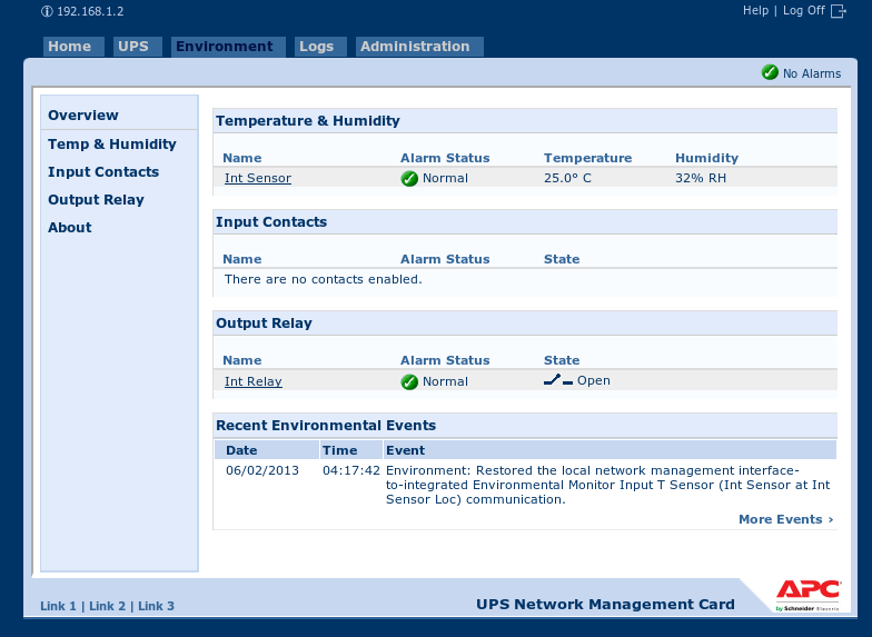
And the UPS seems happy with it:
Good post. I will be going through some of these issues as well..|